
Laser Scanning a Steel Fabrication Plant for Roof and Facade Renovation
Published 5 October 2026
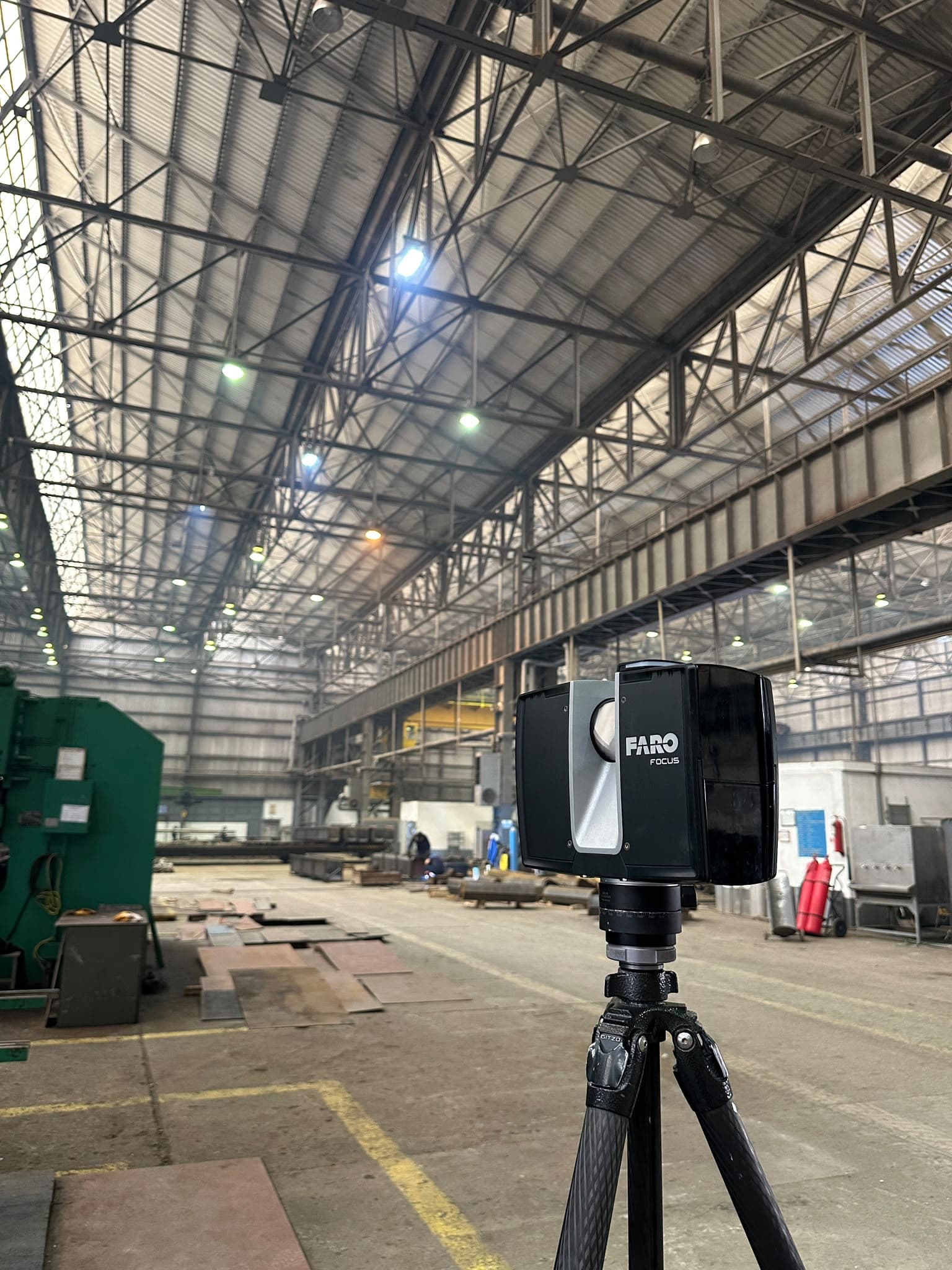
Laser scanning this 12,000 m² steel fabrication plant for renovation took 228 individual scan setups, registered together from inside and outside the building, across areas too hot, too congested with machinery, or too restricted to cover in a single continuous pass. The capture fed two separate deliverables: a structural model of the steel roof trusses, and a facade model to support the renovation's fabrication drawings.
Why 228 scans instead of a handful of wide sweeps
A plant this size would normally need far fewer scanner setups if it were one open, empty volume. This one wasn't: active cutting and press equipment blocked line of sight between bays, some zones ran hot enough to limit how long the scanner could stay in position, and a few sections were access-restricted while work continued around them. Each of those constraints meant moving the scanner more often and covering less area per setup — 228 individual scans was the number that actually got full coverage, not a target picked in advance.
Scan resolution and quality settings for a hot, congested interior
With this many setups needed, scan time per station mattered as much as raw detail. Most of the interior was captured at 1/2 resolution (point spacing) with a 2x quality setting (FARO's noise-reduction exposure averaging) — enough density to resolve individual roof members, purlins, and connection plates, at a scan time per station that made 228 setups achievable in the time available. A handful of areas needing finer connection-plate detail were rescanned at higher resolution specifically for that purpose.
Why not just scan everything at maximum resolution and quality?
- Scan time scales with both settings — at 228 stations, doubling per-station time would have meant a materially longer site programme for detail the roof-structure model didn't need everywhere.
- 1/2 resolution with 2x quality resolves individual structural members and connections cleanly; it's the facade's fine panel-joint detail and specific connection points that get a higher-resolution pass, not the whole building.
- The underlying ranging accuracy doesn't change between settings — resolution and quality control point density and noise, not the scanner's distance-measurement precision.
Merging interior and exterior captures into one registered model
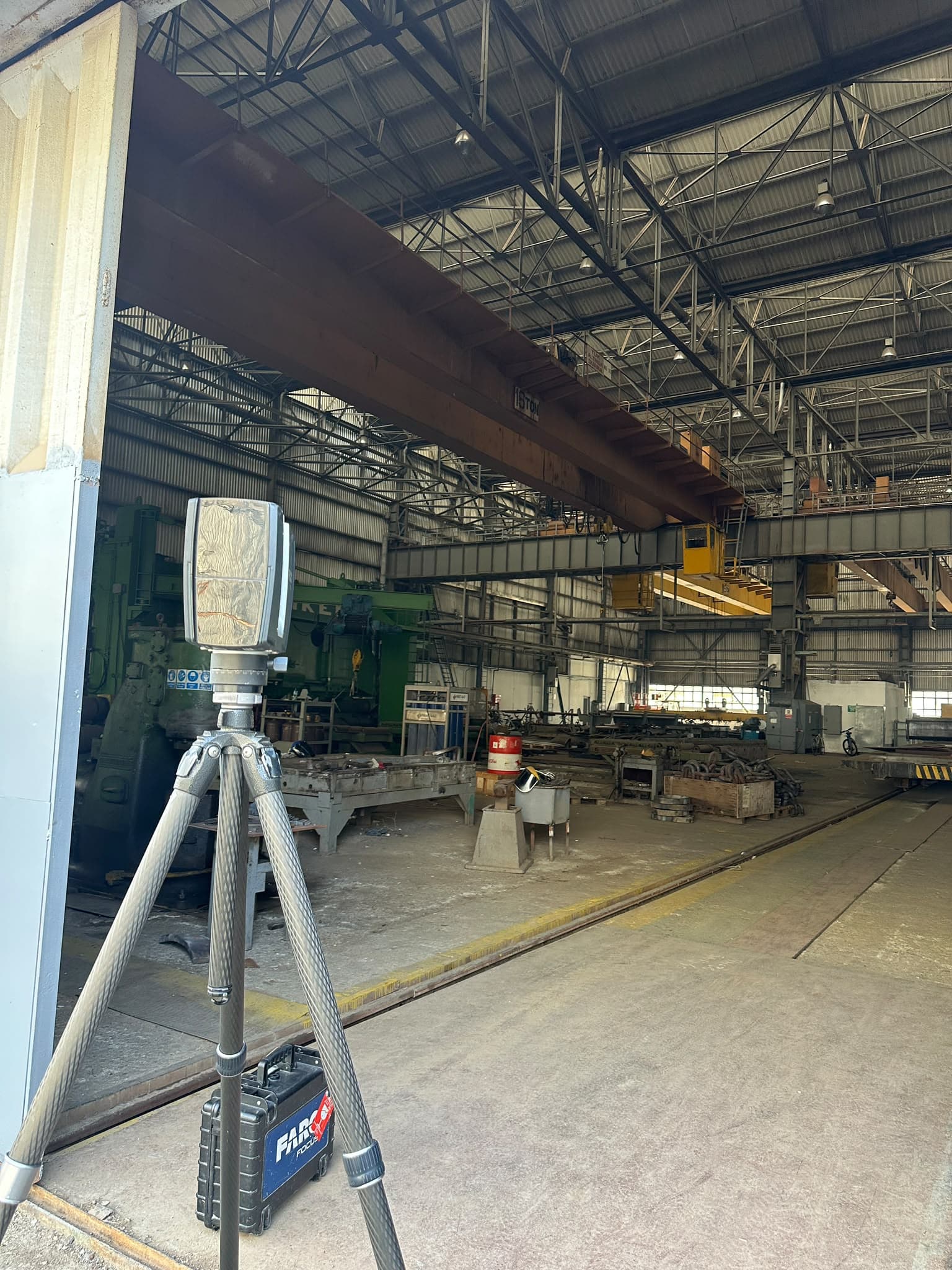
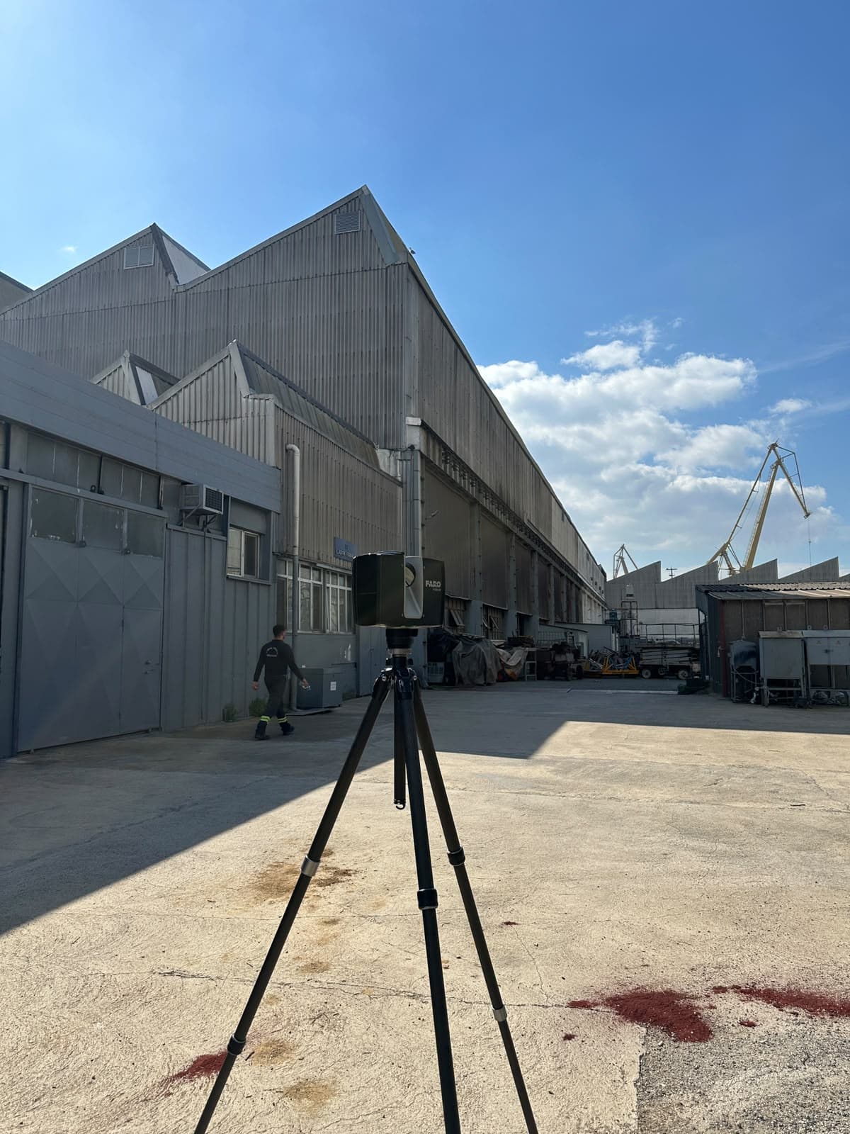
The roof structure and the facade aren't independent deliverables from independent scans — they're two outputs of one registered point cloud that crosses the building's envelope. Exterior scans around the facade were tied into the same control network as the interior bays, so the structural roof model and the facade model share a single coordinate system rather than needing to be manually aligned against each other afterward.
What the renovation team actually needed: two deliverables from one capture
The roof trusses were delivered as a structural model at coordination-to-fabrication grade (LOD 300–400, depending on the member), accurate enough to check against new retrofit or reinforcement design. The facade went into a 3D model for the cladding renovation's own fabrication drawings — the same one-capture, multiple-deliverable approach used across this site's Scan to BIM and Scan to Model work, just applied to a single plant with two distinct renovation scopes at once.
Questions about this article
Can a working steel fabrication plant be scanned without stopping production?
Does scanning at 1/2 resolution instead of full resolution reduce accuracy?
Why did this plant need both a roof structural model and a facade model?
How do you decide how many scan setups a site like this needs?
What LOD does a steel roof structure model like this get delivered at?
Scope your project in one call.
Tell us the site, the deliverable, and the deadline — we'll tell you the tier and turnaround that fits.